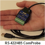
Frontline’s “RS-422/485 ComProbe” – A Portable, Rugged and Easy-to-Use Device for monitoring Asynchronous RS-422/485 communications
 The Serialtest®
analyzer supports the "RS-422/485 ComProbe".
Many laptops and PCs do not have PCMCIA interfaces and the PC
industry has migrated towards USB ports. To help our customers monitor
asynchronous serial communications via their PC's USB port, Frontline
has created the RS-422/485 ComProbe. This device plugs
into a PC's USB port and has screw terminal connectors to tap into the
RS-422/485 circuit.
The Serialtest®
analyzer supports the "RS-422/485 ComProbe".
Many laptops and PCs do not have PCMCIA interfaces and the PC
industry has migrated towards USB ports. To help our customers monitor
asynchronous serial communications via their PC's USB port, Frontline
has created the RS-422/485 ComProbe. This device plugs
into a PC's USB port and has screw terminal connectors to tap into the
RS-422/485 circuit.
The RS-422/485 ComProbe monitors and captures Asynchronous RS-422/485
communications. It does not lose timing and control signal information.
With this interface, Frontline has made its Serialtest analyzer more
rugged, easier to use, portable and transportable. It allows you to
spend more time doing your real job.
I/O Settings
The RS-422/485 ComProbe allows the user plenty of options for
monitoring various serial communication setups. The I/O Settings dialog
allows the user to configure the setup.
The RS-422/485 ComProbe supports data rates up to 921.6Kbps. The user
can pick one of the standard rates in the drop down box in the I/O
Settings dialog. For non-standard rates, the user can simply type in the
value in the box.
The RS-422/485 ComProbe can monitor serial communications with 5, 6, 7
or 8 data bits and with 1, 1.5 or 2 stop bits. The device also supports
all the standard parity types (None, Odd, Even, Mark, Space, and
Ignore).
The user can also choose the bit order on their serial communication
circuit. The choices are either LSB (least significant bit) first or MSB
(most significant bit) first. LSB first is normal, while MSB first is
considered "reversed" from normal. This option reverses the order of the
bits within each byte.
The user can also choose to monitor either DTE only, DCE only or both
DTE and DCE ends of the communication.
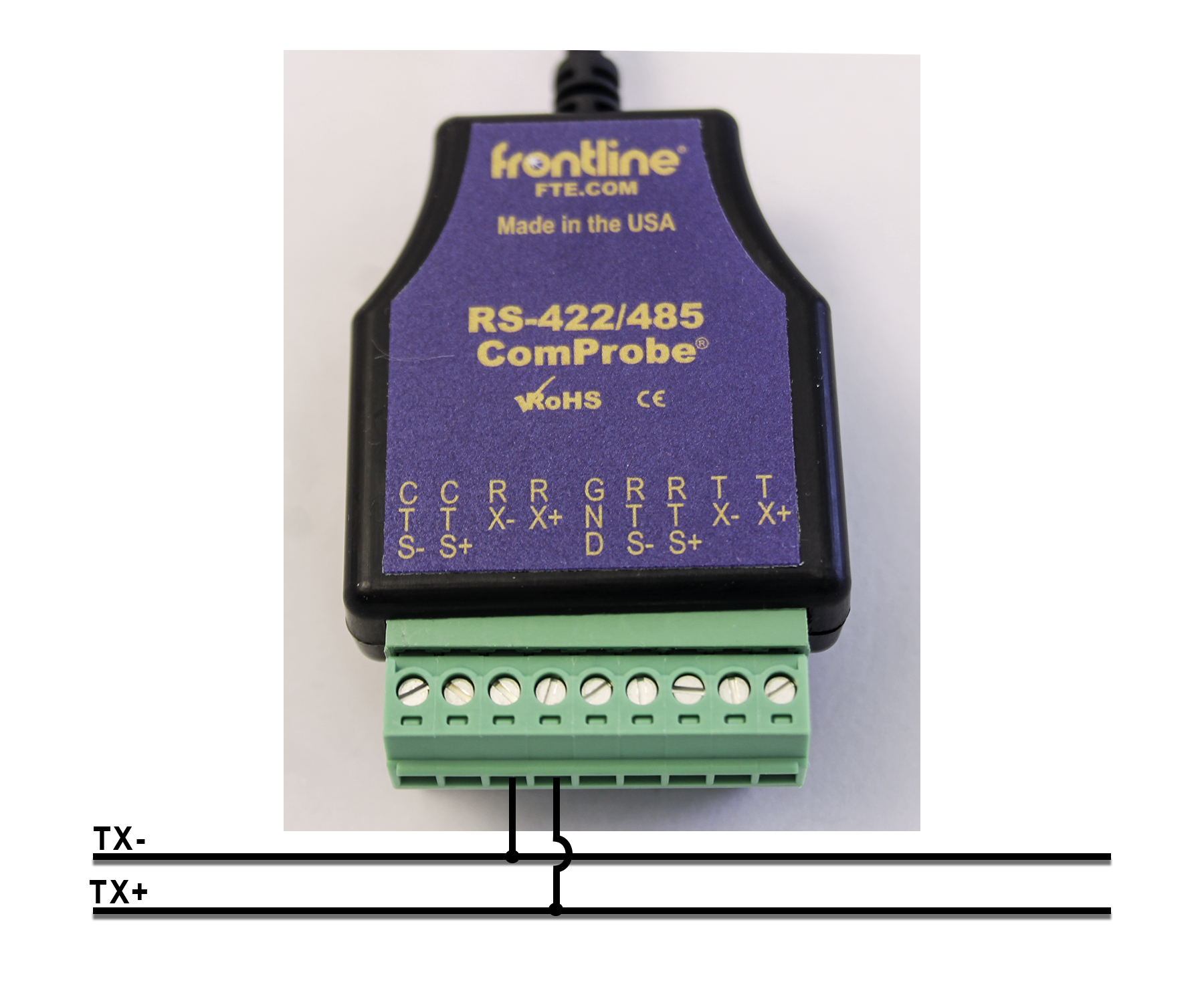 2-Wire Connection
The network transmit lines are connected to the RS-422/485 ComProbe
receive pins.
Tap off the network transmit + line (TX+) and connect it to the RS-422/485
ComProbe RX+ pin, ensuring that the connecting wire is firmly attached by
using the connector screw.
Tap off the network transmit - line (TX-) and connect it to the RS-422/485
ComProbe RX- pin, ensuring that the connecting wire is firmly attached by
using the connector screw.
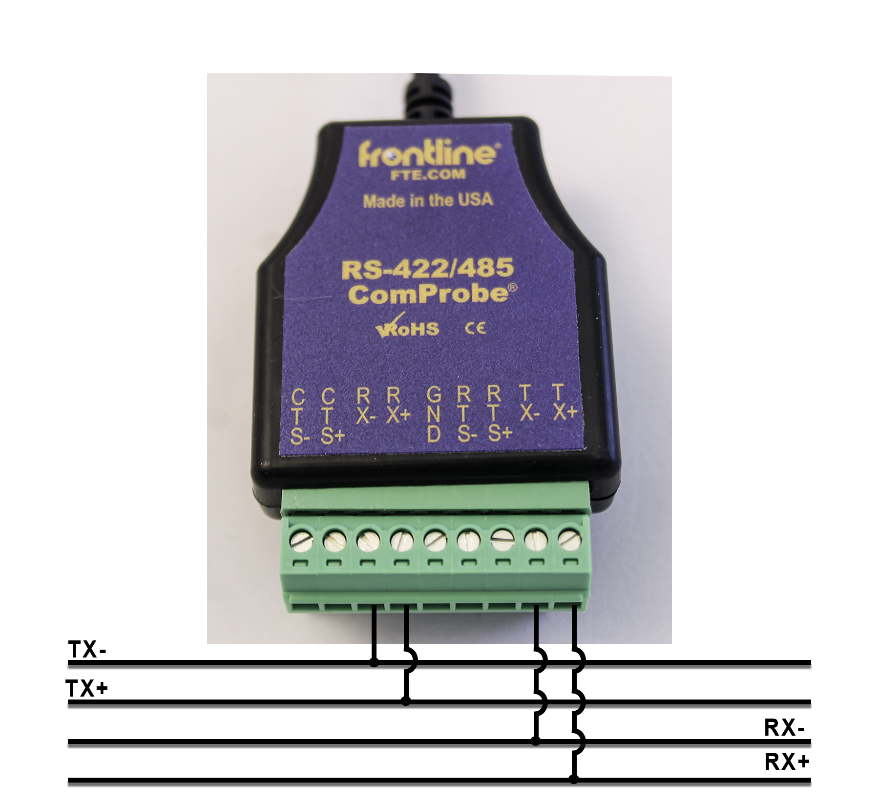 4-Wire Connection
The network transmit lines are connected to the RS-422/485 ComProbe
receive pins, and the network receive lines are connected to the RS-
422/485 ComProbe transmit pins.
Tap off the network transmit + line (TX+) and connect it to the RS-422/485
ComProbe RX+ pin, ensuring that the connecting wire is firmly attached by
using the connector screw.
Tap off the network transmit - line (TX-) and connect it to the RS-422/485
ComProbe RX- pin, ensuring that the connecting wire is firmly attached by
using the connector screw.
Tap off the network receive + line (RX+) and connect it to the RS-422/485
ComProbe TX+ pin, ensuring that the connecting wire is firmly attached by
using the connector screw.
Tap off the network receive - line (RX-) and connect it to the RS-422/485
ComProbe TX- pin, ensuring that the connecting wire is firmly attached by
using the connector screw.
Additional Information
More details about wiring information for these configurations are
available in
this document.
You can order your copy of
Serialtest online.